
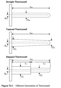
Was Your Process Plant Designed and Built Prior to 2010?
If so, your Thermowells could be at risk of mechanical failure due to fatigue cracking resulting from flow induced vortex excitation.
Most process plants designed and built prior to 2010 would have thermowells selected in accordance with ASME PTC 19.3 1974, which considered a primary flow induced vibration failure mode due to transverse vortex excitation.
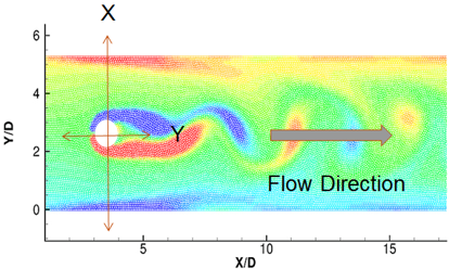
This is where flow over a cylindrical object (thermowell probe), will generate oscillating ‘lift’ forces due to the creation of vortices on one side and then the other at a specific frequency, dependent on the flow velocity and the probe diameter.
To avoid any potential issues, Thermowells basically had to be selected such that the vortex excitation frequency (also known as ‘wake frequency’ was < 80% of the probe natural frequency (vibrating cantilever mode) such that resonant vibration would never occur at any flow rate. Such resonance could be extremely damaging, causing dynamic stresses at the root of the thermowell sufficient to cause the growth of fatigue cracks, ultimately leading to probe failure.
Latest Guidance From ASME PTC 19.3 TW 2010 (and 2016)
However the newer standards ASME PTC 19.3 TW 2010 (and 2016) also consider additional failure modes, including a second vortex excitation mode, this time caused by oscillating ‘drag’ forces and exciting the thermowell probe Inline with the flow at twice the transverse vortex frequency, which means that resonance could occur at 50% of the original critical flow velocity.
The result is that many Thermowells which passed the original Transverse Vortex Excitation criterion will actually fail the newer Inline Vortex excitation criterion.
Energy Institute Method
Assessment Method:
From Section T4 of ‘Guidelines for the avoidance of vibration induced fatigue failure in process pipework‘, 2nd Edition, 2008.
- Considers only Transverse resonance of Thermowell probe
The assessment method is essentially 3 parts:
- Calculate probe natural frequency (and correct for any pipe-wall flexibility) (Fn)
- Calculate maximum vortex excitation frequency (at maximum flow velocity and using minimum thermowell probe diameter) (Fv)
- Assess the ratio of Fv/Fn
- If Fv/Fn > 0.8, then there is a risk of transverse resonance and ‘Likelihood of Failure’ (LOF) = 1.0 = high risk of fatigue damage
- If Fv/Fn < 0.8 then transverse resonance will never occur (at any flow rate) and so LOF = 0.29 (meaning no further action is required)
ASME PTC 19.3TW 2016
Assessment Methods:
- As well as Transverse resonance, the ASME method also considers in-line vortex excitation, which occurs at twice the transverse vortex shedding frequency (or at half the critical flow velocity)
- Considers different materials
- Considers operating temperatures
- Considers fillet radius
- Uses 4 evaluation criteria:
- Wake Frequency < 0.4 x Fn (Inline) and <0.8 x Fn (Transverse)
- Dynamic Stress < fatigue limit for material
- Max static stress must not exceed max allowable stress
- Hydrostatic pressure limit: Internal pressure must not exceed pressure ratings for thermowell tip, shank and flange.
Implications of Inline Vortex Excitation
Whereas previously (Energy Institute method or ASME method pre 2010) the assessment only needed to consider the frequency matching at the worst-case maximum flow velocity, as the Inline excitation will occur at much lower flow rates (50%) of previous velocity critical, we must now also assess all flow rates.
Even if a plant normally operates at high flow rates, we must consider the possible transient resonant conditions during plant start up and shut down, where the inline critical velocities will be passed through.
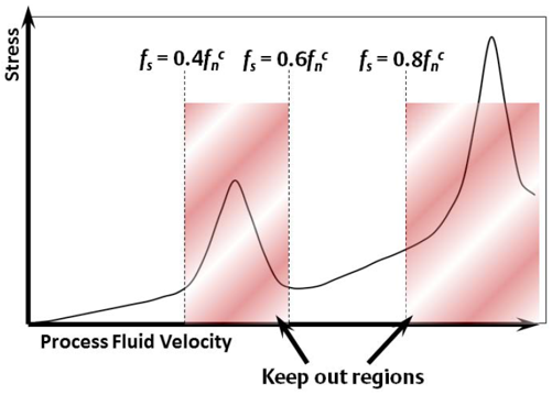
This gives us 2 ‘keep-out’ zones of pipe flow velocity, one to avoid Inline resonance (Fv/Fn 0.4 – 0.6) and one to avoid Transverse resonance (Fv/Fn > 0.8).
Although the Inline excitation will occur at lower flow velocities, therefore having less Kinetic Energy (smaller hydrodynamic excitation forces), the resulting thermowell probe response, amplified by resonance, could produce cyclic stresses large enough to cause ongoing cumulative fatigue damage and eventually failure of the probe.
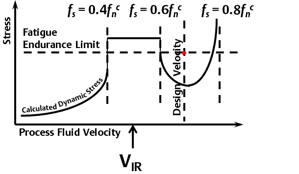
To assess this risk, the ASME method assesses whether these Dynamic Stresses will be higher or lower than a material property known as the ‘Fatigue Endurance Limit’, interpreted as follows:
These 2 scenarios are illustrated in the 2 illustrations below:
- If during a transient (pass-through) flow velocity the highest dynamic stresses at the probe tip are below the Fatigue Endurance Limit for the probe material, then no fatigue damage will be incurred.
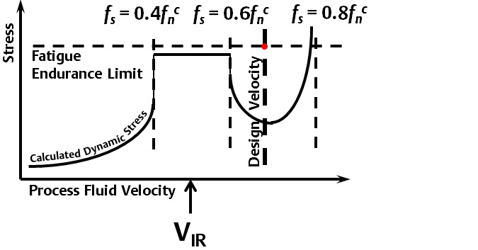
- If during a transient (pass-through) flow velocity the highest dynamic stresses at the probe tip are above the Fatigue Endurance Limit for the probe material, then fatigue damage will occur and the life of the probe will be finite (i.e. will fail after sufficient number of cycles).
VibTech Thermowell Assessment Services
There are a number of ways in which this new resonant vibration risk can be assessed.
VibTech has developed a number of assessment techniques and is currently working with a number of companies performing such assessments, which include:
- Quantitative Assessment – desktop exercise to re-calculate the likelihood of resonant excitation using the new ASME codes
- Onsite In-service Vibration Measurement Techniques – to detect any evidence of inline or transverse thermowell probe resonance based upon external measurements on the accessible thermowell mounting flange with the plant operational. This is often done in conjunction with Finite Element Analysis (FEA) modal predictions.
- Onsite In-service Physical inspection – to detect the presence of any significant cracks in the thermowell probe with the plant operational.
Each of these thermowell assessment methods are detailed further in the following sections:
Quantitative Assessment
These calculations enable the assessment of the likelihood that Thermowell probe resonance will occur at any process flow rates up to the maximum.
They also enable assessment of the following additional factors:
- What type of resonance is expected, Inline or Transverse?
- What frequency will the vibration occur at?
- What are the critical flow velocities for the predicted resonance condition?
- Are the predicted dynamic stresses at resonance likely to be above or below the Fatigue Endurance Limit for the Thermowell probe material/geometry?
- Will the inherent fluid damping be sufficient to suppress any damaging resonant vibration?
In-service Vibration Measurement
Whereas the Quantitative assessment methods will predict whether resonance is likely to occur in theory, it is known that such predictions are often very conservative, and may predict a situation based upon worst-case assumptions. However, actual vibration measurements will identify if resonant vibration is actually occurring in practice and if so, at what severity.
VibTech has been working with operators of LNG sites to develop successful onsite vibration measurement techniques for the identification and assessment of resonant thermowell vibration.
External vibration measurements have been shown to be highly effective at identifying resonant vibration amplitude and frequency.
VibTech has used Finite Element Analysis (FEA) to aid the interpretation and assessment of the external vibration measurements. This is extremely important for the following reasons:
- Validate the suspected resonance by correlation of the measured frequency and direction (inline or transverse) with predicted mode shapes for the Thermowell probe and Nozzle assembly.
- Use the FEA to calibrate the external vibration measurements into dynamic ‘hot-spot’ stresses at inaccessible internal locations where the thermowell probe meets the mounting flange (or anchor point).
In-service Physical Inspection
Whereas the in-service vibration measurements will indicate whether fatigue damage is likely to be occurring, they are unable to identify the extent of any historical or ongoing fatigue damage.
VibTech has been working with operators of LNG sites to develop successful onsite physical inspection techniques which can be carried out on live thermowells in order to provide a clear unambiguous indication of the presence of any significant cracking.
Concept:
The central bore of the TW-Probe (surrounding the internal Thermocouple element) should be gas tight and contain only air at ambient pressure.
A ‘through-wall’ crack in the TW probe root will result in a pressurisation of the TW bore with Natural gas.
Loosening or removing the external Temperature Element connection will release any increased pressure, where any contained natural gas will be detectable.
Thermowell Assessment White Paper
VibTech offers a comprehensive range of Thermowell Assessment Services
VibTech has written a detailed white paper covering all 3 stages of thermowell assessment mentioned above, including real-life case studies of where the techniques have been used on process plants.
For further information about VibTech’s range of Thermowell Assessment Services, or to request a copy of the VibTech Thermowell Assessment White Paper, please contact us via our ‘Contact Us’ page:More Information